This circuit provides a means to add up to 8 DMA devices to an 1802 based computer. The selector also allows you to specify whether a DMA request will trigger the DMA_IN or DMA_OUT of the cpu.
Note: This circuit is theoretical, I have not yet tested this in in either hardware or simulation
Theory of operation
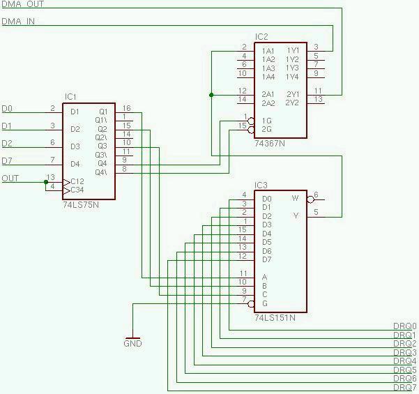
IC1 is a 4 bit latch that is used to hold the selected DMA device as well as the selected direction. D0-D2 of the processor are used to select which DMA device, while D7 is used to select direction. IC1 will latch its inputs when OUT goes from low to high. OUT must either come from the decoded N lines, or as a decoded port from the multi-port controller.
IC2 provides the gating to trigger either DMA_IN or DMA_OUT of the 1802. When Q4 if IC1 is low then gate 1a is allowed to pass its signal on to DMA_IN while gate 2a is in the high impedance state. When Q4 of IC1 is low, the situation is reversed. Therefore when a 0 exists on D7 when writing the DMA selector, DMA_IN operation will be selected.
IC3 is a one of 8 data selector. The Q1,Q2, and Q3 outputs from IC1 are used to select which of the DRQ signals will appear at the Y output.